The B&W Learning Center
Leading the world in clean power production technology
Finding the Root Cause of Boiler Tube Failures
Finding the Root Cause of Boiler Tube Failures
Have you ever repaired a boiler tube leak, put the unit back into service, only to be forced offline by another leak?
Identifying and correcting the root cause of tube failures is essential to help lessen the chance of future problems. A comprehensive assessment is the most effective method of determining the root cause of a failure. A tube failure is usually a symptom of other problems. To fully understand the cause of the failure, you must investigate all aspects of boiler operation leading to the failure in addition to evaluating the failure itself.
When you experience tube failures, take advantage of B&W’s expertise to help you determine and eliminate the root cause of the problem. Our experienced field service engineers can help gather all the pertinent information. Better yet, let us help put together a complete condition assessment program to help eliminate tube problems before failures occur.
The following boiler tube failure mechanisms are some of the most common that occur on modern operating boilers. We’ve organized these into three sections and have included their symptoms, possible causes, the components typically affected and solutions:
- Waterside failure mechanisms
- Fireside failure mechanisms
- General failure mechanisms
Waterside failure mechanisms
Caustic attack
Symptoms: Localized wall loss on the inside diameter (ID) surface of the tube, resulting in increased stress and strain in the tube wall.
Causes: Caustic attack occurs when there is excessive deposition on ID tube surfaces. This leads to diminished cooling water flow in contact with the tube, which in turn causes local under-deposit boiling and concentration of boiler water chemicals. If combined with boiler water chemistry upsets of high pH, it results in a caustic condition which corrosively attacks and breaks down protective magnetite.
Components typically affected: Furnace wall tubes or any inclined tube.
Solutions: To prevent reoccurrence of caustic gouging, operators should prevent accumulation of excessive deposits and control water chemistry so that boiler water does not locally form caustic in areas where chemicals concentrate. In some instances, where caustic gouging along the top of a sloped tube is associated with steam-water separation, such separation can be avoided by use of ribbed tubes. Controlling water chemistry can be achieved by assuring appropriate feedwater chemistry with phosphate boiler water treatments.

Oxygen pitting
Symptoms: Aggressive localized boiler tube corrosion and loss of tube wall. Pits can act as stress-concentration sites which can be initiation points for stress-related corrosion mechanisms
Causes: Oxygen pitting occurs with the presence of excessive oxygen in boiler water. It can occur during operation as a result of in-leakage of air at pumps, or failure in operation of preboiler water treatment equipment. This also may occur during extended out-of-service periods, such as outages and storage, if proper procedures are not followed in layup.
More generalized oxidation of tubes during idle periods is sometimes referred to as out-of-service corrosion. Wetted surfaces are subject to oxidation as the water reacts with the iron to form iron oxide.
Components typically affected: During outage periods, flooded or non-drainable surfaces, such as superheater loops or sagging horizontal superheater and reheater tubes and supply lines, are most susceptible; also, when poorly deaerated water is used for startup or for accelerated cooling of a boiler. On operating boilers, it is most prevalent near pre-boiler feedwater heaters and economizers.
Solutions: Follow proper layup procedures during boiler outages and improve oxygen control during boiler startups and boiler operation.

Hydrogen damage
Symptoms: Intergranular micro-cracking. Loss of ductility or embrittlement of the tube material leading to brittle catastrophic rupture.
Causes: Most commonly associated with excessive deposition on ID tube surfaces, coupled with a boiler water low pH excursion. Water chemistry upset, such as what can occur from condenser leaks, particularly with salt water cooling medium. Leads to acidic (low pH) contaminants that can be concentrated in the deposit. Under-deposit corrosion releases atomic hydrogen which migrates into the tube wall metal, reacts with carbon in the steel (decarburization), and causes intergranular separation. The failures are usually, though not necessarily, associated with a heavy scale on the tube surface.
Components typically affected: Usually occurs in regions of high heat flux and is generally confined to waterwall tubes.
Solutions: Prevention of scale on the water side of the tubing, as well as tight control of the water chemistry, can help prevent hydrogen damage.

Acid attack
- Symptoms: Corrosive attack of the tube metal surfaces resulting in an irregular pitted or swiss cheese appearance on the tube ID.
- Causes: Most commonly associated with poor process control during boiler chemical cleanings, inadequate cleaning of residual acid, and/or inadequate post cleaning passivation.
- Components typically affected: Waterwall tubes.
- Solutions: Control water chemistry, watch for chemical hideout, maintain proper controls during boiler chemical cleanings.
Stress corrosion cracking
Symptoms: Failures are characterized by a thick wall, brittle-type crack. May be found at locations of higher external stresses, such as near attachments. Most commonly associated with austenitic (stainless steel) superheater materials and can lead to either transgranular or intergranular crack propagation in the tube wall. Stress corrosion (or stress-assisted corrosion) cracks are typically branched with numerous small secondary cracks associated with the main fracture area.
Causes: It occurs where a combination of high-tensile stresses and a corrosive fluid are present. The damage results from cracks that propagate from the ID. The source of corrosive fluid may be carryover into the superheater from the steam drum or from contamination during boiler acid cleaning if the superheater is not properly protected.
Components typically affected: Stainless steel superheater and reheater tubes.
Solutions: Avoid water carryover control hydrotest methods, flush after cleaning.
Waterside corrosion fatigue
Symptoms: ID initiated, wide transgranular cracks which typically occur adjacent to external attachments. Failures are catastrophic, thick-lipped failures that initiate from ID cracks that are oriented perpendicular to the direction of the stress
Causes: Tube damage occurs due to the combination of thermal fatigue and corrosion. Corrosion fatigue is influenced by boiler design, water chemistry, boiler water oxygen content, and boiler operation. A combination of these effects leads to the breakdown of the protective magnetite on the ID surface of the boiler tube. Loss of this protective scale exposes the tube to corrosion. The problem is most likely to progress during boiler start-up cycles.
Components typically affected: The locations of attachments and external weldments, such as buckstay attachments, seal plates and scallop bars, are most susceptible.
Solutions: Minimize number of cycles, minimize constraints on tubes, lower dissolved oxygen on start-up.

Fireside failure mechanisms
Fuel ash corrosion
Symptoms: External tube wall loss and increasing tube strain. Tubes commonly have a pock-marked appearance when scale and corrosion products are removed.
Causes: Fuel ash corrosion is a function of the ash characteristics of the fuel and the boiler design. It is usually associated with coal firing, but can also occur for certain types of oil firing. The ash characteristics are considered in the boiler design when establishing the size, geometry and materials used in the boiler. Combustion gas and metal temperatures in the convection passes are important considerations. Damage occurs when certain coal ash constituents remain in a molten state on the superheater or reheater tube surfaces. This can be highly corrosive.
Components typically affected: Superheaters and reheaters.
Solutions: The most straightforward method to reduce fuel ash corrosion is by using materials with higher chromium concentrations. In general, materials with >20% Cr have significantly lower fuel ash corrosion rates than materials with <20% Cr. The installation of austenitic stainless steel tube shields has been successfully implemented to reduce fuel ash corrosion in boiler locations that exhibit very corrosive conditions. Additions of calcium and magnesium to the fuel can also help mitigate fuel ash corrosion.
High-temperature oxidation
Similar in appearance and often confused with fuel ash corrosion, high-temperature oxidation can occur locally in areas that have the highest outside diameter (OD) surface temperature relative to the oxidation limit of the tube material. Determining the root cause of the mechanisms of fuel ash corrosion or high-temperature oxidation is best accomplished by tube analysis and evaluation of scale and deposits.
Waterwall fireside corrosion
Symptoms: External tube metal loss (wastage) leading to thinning and increasing tube strain.
Causes: Corrosion occurs on external surfaces of waterwall tubes when the combustion process produces a reducing atmosphere (substoichiometric). This is common in the lower furnace of recovery boilers. For units firing coal, boilers having maladjusted burners or utilizing staged firing (with overfire air ports) can be more susceptible to larger localized regions possessing a reducing atmosphere, resulting in increased corrosion rates.
Components typically affected: Waterwall tubes.
Solutions: The primary method employed to combat furnace wall boiler tube corrosion is the use of high-Ni/high-Cr weld overlays on tubes in the locations that are experiencing the worst corrosion. Corrosion-resistant thermal sprays may also be considered for this application.
Fireside corrosion fatigue
Symptoms: Tubes develop a series of cracks that initiate on the OD surface and propagate into the tube wall. Since the damage develops over longer periods, tube surfaces tend to develop appearances described as elephant hide, alligator hide or craze cracking. The damage is most commonly seen as a series of circumferential cracks.
Causes: The damage initiation and propagation result from corrosion in combination with thermal fatigue. Tube OD surfaces experience thermal fatigue stress cycles which can occur from normal shedding of slag, sootblowing, or from cyclic operation of the boiler. Thermal cycling, in addition to subjecting the material to cyclic stress, can initiate cracking of the less elastic external tube scales and expose the tube base material to repeated corrosion.
Components typically affected: This type of boiler corrosion fatigue is commonly found on furnace wall tubes of coal-fired once-through boiler designs, but has also occurred on tubes in drum-type boilers.
Solutions: Reduce the ramp rates during start-up and shut-down to reduce the thermal stresses. Optimize sootblowing operations to minimize thermal stresses.

Erosion
Symptoms: Tube experiences metal loss from the OD of the tube. Damage will be oriented on the impact side of the tube. Ultimate failure results from rupture due to increasing strain as tube material erodes away.
Causes: Erosion of tube surfaces occurs from impingement on the external surfaces. Firing high ash fuels, such as western U.S. subbituminous coal, may lead to more erosion, slagging and fouling problems. The erosion medium can be any abrasive in the combustion gas flow stream, but is most commonly associated with impingement of fly ash or sootblowing steam. In cases where sootblower steam is the primary cause, the erosion may be accompanied by thermal fatigue.
Components typically affected: Common near sootblowers; on the leading edges of economizers, superheaters and reheaters; and where there are vortices or around eddies in the flue gas at changes in gas velocity or direction.
Solutions: For fly ash erosion, distribute flow evenly through the boiler and consider burning a lower ash fuel. Optimize sootblowing operations to minimize damaging impingement.

Mechanical fatigue
Symptoms: Damage most often results in an OD initiated crack. The failures tend to be localized to the area of high stress or constraint.
Causes: Fatigue is the result of cyclical stresses in the component. Distinct from thermal fatigue effects, mechanical fatigue damage is associated with externally applied stresses. Stresses may be associated with vibration due to flue gas flow or sootblowers (high-frequency, low-amplitude stresses), or with boiler cycling (low-frequency, high-amplitude stress mechanism).
Components typically affected: Fatigue failures will most often occur at areas of constraint such as tube penetrations, welds, or supports.
Solutions: Identify and minimize the source of thermal or mechanical cyclic stresses.
General failure mechanisms
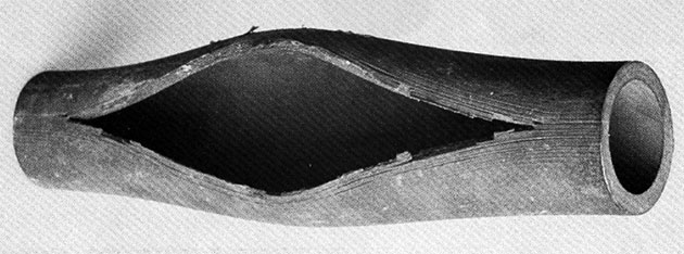
Short-term overheat
Symptoms: Failures result in a ductile rupture of the tube metal and are normally characterized by the classic fish mouth opening in the tube where the fracture surface is a thin edge.
Causes: Short-term overheat failures are most common during boiler start-up. Failures result when the tube metal temperature is extremely elevated from a lack of cooling steam or water flow. A typical example is when superheater tubes have not cleared of condensation during boiler start-up, obstructing steam flow. Tube metal temperatures reach combustion gas temperatures of 1600F (870C) or greater which lead to tube failure.
Components typically affected: Furnace wall tubes, superheaters, reheaters.
Solutions: Ensure that no blockages exist within the tubes and bends. Follow prescribed shut-down and start-up procedures to boil out any condensate.

Long-term overheat
Symptoms: The failed tube has minimal swelling and a longitudinal split that is narrow when compared to short-term overheat. Tube metal often has heavy external scale build-up and secondary cracking.
Causes: Long-term overheat occurs over a period of months or years. Superheater and reheater tubes commonly fail after many years of service as a result of creep. During normal operation, alloy superheater tubes will experience increasing temperature and strain over the life of the tube until the creep life is expended. Furnace water wall tubes can also fail from long-term overheat. In the case of water wall tubes, the tube temperature increases abnormally, most commonly from waterside problems such as deposits, scale, or restricted flow. In the case of either superheater or water wall tubes, eventual failure is by creep rupture.
Components typically affected: Furnace wall tubes, superheaters, reheaters.
Solutions: Correct flame impingement issues on waterwall tubes. Correct water/steam circulation maldistribution issues. Chemically clean tubes to improve heat transfer. Balance furnace/flue gas temperatures with circulation to reduce the tube temperatures.
Graphitization
Symptoms: Failure is brittle with a thick edge fracture.
Causes: Long-term operation at relatively high metal temperatures can result in damage in carbon steels of higher carbon content, or carbon-molybdenum steel, particularly in weld heat affected zones (HAZ), and result in a unique degradation of the material. These materials, if exposed to excessive temperature, will experience dissolution of the iron carbide in the steel and formation of graphite nodules, resulting in a loss of strength and eventual failure. Sudden tube failures can occur with no warning.
Components typically affected: Most prevalent in the portions of the superheater and reheater that operate at relatively low temperatures (such as piping).
Solutions: Use available graphitization prediction curves to determine locations that are at greatest risk. Evaluate samples from locations that are at greatest risk. Replace components that display evidence of graphitization.
Dissimilar metal weld (DMW) failure
Symptoms: Failure is preceded by little or no warning of tube degradation. The material fails at the ferritic side of the weld, along the weld fusion line. A failure tends to be catastrophic as the entire tube will fail across the circumference of the tube section.
Causes: DMW describes the butt weld where an autenitic (stainless steel) material joins a ferritic alloy (such as SA213T22) material. Failures at DMW locations occur on the ferritic side of the butt weld. These failures are attributed to several factors: high stresses at the austenitic-to-ferritic interface due to differences in expansion properties of the two materials, excessive external loading stresses and thermal cycling, and creep of the ferritic material. Failures are a function of operating temperatures and unit design.
Components typically affected: Superheater and reheater outlet bank connections to the outlet headers.
Solutions: Replace DMWs with a shop-welded Dutchman or a field weld that utilizes a Ni-based weld metal. Ensure that locations where DMWs are present are not being overheated during operation.