The B&W Learning Center
Leading the world in clean power production technology
Electrostatic Precipitator
Basics of Electrostatic Precipitator (ESP) Operation
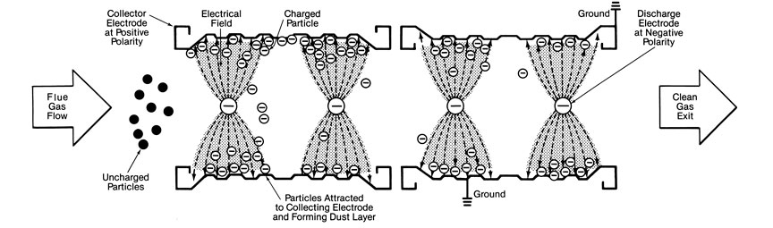
A dry electrostatic precipitator (ESP) electrically charges the ash particles and imparts a strong electric field in the flue gas to collect and remove them. An ESP is comprised of a series of parallel, vertical metallic plates (collecting electrodes) forming lanes through which the flue gas passes. Centered between the collecting electrodes are discharge electrodes which provide the particle charging and electric field. This figure shows a plan view of a typical ESP section which indicates the process arrangement.
A transformer-rectifier (T-R) set along with an automatic voltage controller (AVC) supply the high-voltage and unidirectional current to the discharge electrodes. Several T-R sets are normally required to power a precipitator.

Typical dry ESP configuration
Charging
The collecting electrodes are typically electrically grounded and connected to the positive polarity of the high-voltage power supply. The discharge electrodes are suspended in the flue gas stream and are connected to the output (negative polarity) of a high-voltage power source. An electric field is established between the discharge and collecting electrodes, and the discharge electrodes will exhibit an active glow, or corona. As the flue gas passes through the electric field, the particulate takes on a negative charge.

Corona on high-voltage ESP wire
Collecting
The negatively charged particles are attracted toward the grounded collecting electrodes and migrate across the gas flow. Some particles are difficult to charge, requiring a longer residence time. Other particles are charged easily and driven toward the plates, but also may lose the charge easily after contacting the grounded CE, requiring recharging and recollection. Resistivity is an inverse measure of a particle’s ability to accept and hold a charge. Lower resistivity indicates improved ability to accept a charge and be collected in an ESP.
Gas velocity between the plates is also an important factor in the collection process since lower velocities permit more time for the charged particles to move to the CEs and reduce the likelihood of migrating back into the gas stream (re-entrainment). A series of CE and DE sections is generally necessary to achieve overall particulate collection requirements.
The ash particles form an ash layer as they accumulate on the collection plates. The particles remain on the collection surface due to the forces from the electric field as well as the cohesive forces between particles. These forces also tend to make the individual particles agglomerate, or cling together.
Cleaning
The ash layer must be periodically removed. The most common removal method is rapping which involves mechanically striking the collection surface to dislodge the ash. It is important that the rapping frequency allows an adequate thickness of dust to collect on the plates so that the accumulated ash can be removed in sheets. This sheeting is important to prevent the re-entrainment of individual particles into the flue gas stream, requiring additional recharging and recollection downstream.
While most of the particles are driven to the CEs, particles in close proximity to the DEs receive a positive charge and are therefore attracted to the DEs. If allowed to accumulate, the ash layer would suppress corona generation. A separate rapping system is therefore used to remove deposits from the DEs and maintain proper operation.
The dislodged sheets fall from the collection surface into hoppers. Once the particulate has reached the hopper, it is important to ensure that it remains there in bulk form with minimal re-entrainment until the hopper is emptied. See our article on ash removal basics in the Learning Center.
Applications
Because coal is a common fuel for steam generation, collection of the coal ash particles via an ESP is historically the most commonly used collection system. To meet the particulate control regulations for utility units, as well as the required high collection efficiency, special attention must be given to the details of precipitator sizing, powering, electrical controls, rapping, flow distribution and gas bypass around the collector plates. The result will be a collector that can continuously operate to meet the particulate outlet emissions requirements. ESPs have also been installed on boilers that fire oil as their principal fuel and operate at emission levels similar to ESPs operating on coal-fired units.
In addition to coal, industrial steam generating units where ESPs are successfully applied include municipal refuse incinerators, and wood or bark-fired boilers. For these applications, the ash in the flue gas is typically more easily collected than coal fly ash so an ESP of modest size will easily collect the particulate.
In the pulp and paper industry, precipitators are used on power boilers and chemical process recovery boilers. The power boiler particulate emissions requirements are the same as those for the industrial units using the same fuels. For recovery boilers, precipitators are used to collect the residual salt cake in the flue gas. A recovery boiler is a unique application for a precipitator due to the small particulate size and the tendency for the cohesive ash particles to stick together. The resistivity of the particulate is low, so it is collected easily in the ESP. However, the fine particulate can also cause problems with the generation of effective corona by the DEs due to an effect called space charge.