The B&W Learning Center
Leading the world in clean power production technology
Assessing Structural Integrity and Remaining Life of Boiler Tubing
Power plant operators looking to get the most out of their existing steam generating systems are constantly faced with the decision to “run, repair or replace” their equipment and prevent unplanned outages that impact operations. As boiler tube failure is the leading cause of unscheduled availability loss, an important preventive measure is testing boiler tubes to analyze their condition and gauge their remaining useful life. But what happens when you send your tubes out for testing, and what can the analyses tell you that you don’t already know?
The following steps are based on protocols at B&W’s metallurgical testing lab at its facility in Copley, Ohio.
Step 1: Customers are given guidelines for recommended quantities and sizes of tubes to submit for testing.
Step 2: Upon receipt of the tube samples, as-received photographs are taken to document their overall visible condition, and size measurements are recorded.
Step 3: An initial evaluation and documentation of hot side and cold side outer diameter (OD) and inner diameter (ID) tube condition is taken, and any evidence of degradation is documented.
Step 4: Dimensional analysis -- based on OD and wall thickness at a minimum of four circumferential positions at differing locations along the length of each sample -- is performed.
Step 5: Segments are removed from each sample for chemical analysis to establish conformance with the requirements of the specified grade of material. The chemical analyses are typically performed using optical emission spectroscopy (OES) or inductively coupled plasma (ICP) analytical techniques.

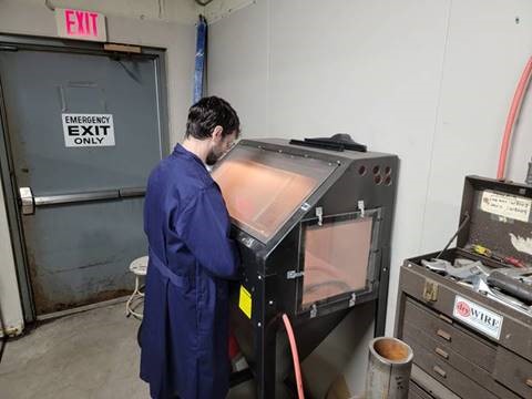
Glass bead blasting a tube sample
Step 6: Tube samples are sectioned with a band saw and/or abrasive cut-off wheels to remove samples for metallographic evaluation, deposit weight density (DWD) measurements on furnace wall tubes, or examination of the ID surface of the samples. DWD measurement is conducted in accordance with ASME D3483 with either Test Method A (scraping method) or Method C (glass bead blasting) for removal of the ID deposits.
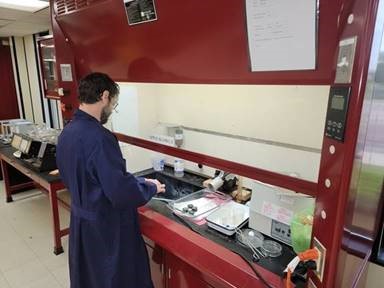
Step 7: Segments removed for metallographic examination are then mounted in a polymeric material, surface ground and polished, and etched to delineate the material’s microstructure.

Etching a metallographic mount to reveal microstucture
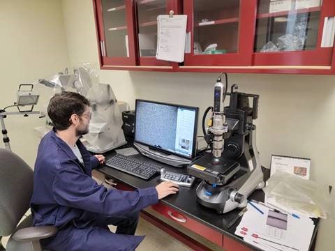
Step 8: Photomicrographs are taken of the etched metallographic mounts on a high-resolution digital microscope.
Step 9: Hot side and cold side metallographic data points are analyzed for evaluation, including:
- Microstructure
- Decarburization
- Graphitization
- Creep
- ID/OD oxide/scale thickness and evaluation
- ID/OD surface condition
- Grain boundary/corrosion/cracking evaluation

Microscope examination of metallographic mount’s microstructure
Step 10: Rockwell B or C hardness (HRB/HRC) determinations are typically made at the mid-wall position of the tube cross-section to compare with specified requirements. If necessary, Vickers microhardness measurements are conducted on the metallographic mounts.
Step 11: Remaining Life Assessment (RLA) and Condition Assessment (CA) analysis is performed. The RLA of superheater and reheater tube samples is based on Larson-Mill Parameter (LMP) vs. stress -- ID oxide layer thickness, calculated mean tube temperature, exposure time, and tube material grade. The CA/RLA of furnace and economizer tube samples is based on operating hoop stress, temperature, creep-rupture curve / LMP, microstructure degradation, ID/OD attack, and/or wall loss rates.
Step 12: A comprehensive engineering report is prepared providing a summary of the findings, a discussion of the results, conclusions and recommendations.
Typical recommendations can include:
- RUN: Results indicate the submitted samples show a substantial estimated remaining life and are suitable for continued service.
- REPAIR: Results indicate tubes are not adequate for current service and material should be upgraded.
- REPLACE: Results shows creep damage and/or wall thickness has been reduced below the recommended threshold and the tubing should be replaced.
Lab analyses can identify failure mechanisms and determine recommendations to assist in maintenance decisions. Analyses is recommended every 3-5 years.
Read more about B&W's complete condition assessment and in-house laboratory services.