The B&W Learning Center
Leading the world in clean power production technology
Gas-Liquid Contact Devices
Absorber Gas-Liquid Contact Devices
SO2 removal in a limestone forced oxidized (LSFO) wet scrubber is controlled by how much SO2 can be absorbed per unit volume of recirculated slurry (lb SO2 per gallon, or kg per liter). This is referred to as absorption. SO2 absorption is limited by the amount of solid- and liquid-phase alkalinity provided in each gallon of slurry. The absorption is also a function of the physical design of the absorber, which sets the gas-slurry contact area. Better contacting exposes more of the slurry to the gas and the increased exposure allows more of the alkalinity in each gallon of slurry to be utilized.
The most common type of wet FGD absorber is the spray tower. Many of these spray towers are open tower configurations where the flue gas enters the tower horizontally and turns 90 degrees into a vertical open cylindrical vessel with multiple levels of spray headers. The SO2 removal process begins as hot flue gas enters the absorber tower where it is cooled and saturated by the slurry. The flue gas then flows upward through the absorber spray zone, where slurry is sprayed countercurrently to the flue gas flow. Unequal distribution of flue gas across the absorber cross section is a common concern. This is caused by the high velocity of flue gas entering the absorber which causes the flue gas to hug the walls of the absorber resulting in gas bypassing the spray headers. The SO2 removal efficiency of an open spray tower can be upgraded by adding wall rings or an absorber tray. The structural aspects of adding wall rings or an absorber tray must be considered in any such retrofit.
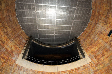
Wall rings improve SO2 collection efficiency by reducing the gas bypass in an open spray tower which results from the tendency of the flue gas to hug the walls of the absorber. Wall rings also push out the slurry that runs down from the walls back into the gas stream, improving the contact between the slurry and flue gas. Figure 1 shows a typical wall ring retrofit in a wet FGD.

Fig. 1 Wall ring retrofit
Retrofitting an absorber tray into an open spray tower is an effective way to maximize the contact between the flue gas and the slurry. The tray maximizes the contact between the gas and the slurry due to the vigorous frothing action that occurs on the tray. The absorber tray also evenly distributes the flue gas flow across the absorber cross-section, promoting optimum contact as the flue gas passes through the absorber spray levels. Figure 2 illustrates gas velocity profiles of the flue gas at the spray levels in an open spray tower compared to an absorber tower with a tray. As can be seen, the addition of a tray eliminates the high-velocity areas along the absorber wall.

Fig. 2 Gas velocity profiles of the flue gas at the spray levels in an open spray tower (left) compared to an absorber tower with a tray (right).
The use of an absorber tray can eliminate the need for the addition of a spray level in the absorber. The additional fan power required from the increased gas-side system pressure drop of the tray is typically offset by a reduction in pumping power associated with the lower L/G required to achieve a given SO2 removal efficiency. For moderate SO2 removal improvements, the absorber tray retrofit can allow the plant to use one less spray level and spray pump per absorber. This results in decreased operating and maintenance costs. Figure 3 shows a tray installed above the gas inlet of an absorber.
Depending upon the target removal efficiency and configuration of the existing wet FGD module, installing two trays may also be considered as an option to achieve the most optimized upgrade to the system. Full-scale field tests have shown the benefit of adding an absorber tray to an open spray tower. Figure 4 illustrates the SO2 removal efficiency increase in the same absorber tower with and without an absorber tray.

Fig. 4 SO2 removal efficiency increase in the same absorber tower with and without an absorber tray.