The B&W Learning Center
Leading the world in clean power production technology
ESP Collection Efficiency
Factors that Affect ESP Collection Efficiency and Ways to Improve Performance
This article will review several design and operational problems that will negatively affect the collection performance of an ESP. It will also outline potential modifications to help improve performance and efficiency.
Aspect ratio
The aspect ratio of a precipitator compares the horizontal run of collecting surface to the height of the precipitator. In general, the aspect ratio of a well-designed ESP should be greater than 1.0. In the example shown here, the aspect ratio would equal 0.8, not a good design for the most effective collection performance.

Gas velocity
The velocity which the flue gas passes through a precipitator will affect its collection performance. A faster velocity of particles will result in reduced collection efficiency. In general, a velocity of 3 to 5 ft/sec is desirable which would allow for an approximate treatment time of greater than 10 seconds. Flue gas velocities faster than this will lessen the ESP’s performance.

Specific collection area
Specific collection area (SCA) is a measure of the total surface area of all collecting plates divided by the volumetric flow of flue gas. Therefore, any change to either the surface area or the gas flow volume can have either a positive or negative impact on collection efficiency. An ESP is sized to meet a required performance or particulate collection efficiency. The sizing procedure determines the amount of collection surface for the specified performance. An improperly designed precipitator with inadequate collection surface will not be able to reach or sustain required collection of the particulate load unless more power per square feet of collecting surface can be applied. However, more power is not a solution in every application.
Modifications for improved performance
Solutions for these three design limitations include the following:
- Adding another field in series
- Increasing the height of the ESP
- Adding another ESP in parallel or series
- Rebuilding the existing ESP
Space constraints, both within the existing ESP enclosure and the footprint space available at the site, must be considered in evaluating recommended upgrade options.
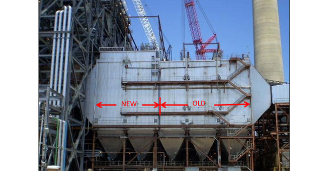
The photo below shows two ESP fields converted to a top-rapped American design to increase ESP collection efficiency. The top-rapped fields have more electrical fields (more power) than the original European design. This conversion replaces the European design of using a tumbling hammer rapper system, which is internal to the ESP enclosure and thus requires space, with a top-rapped design which places the high-voltage electrical and rapper systems above the ESP compartment. In some cases, this can accomplish the required increased collection efficiency without increasing the size of the existing ESP.
As shown in the next photo, an entire new ESP can be added to increase the specific collection area. While this alternative is feasible in some applications, it may be cost prohibitive as it would require significant outage time.

Completely rebuilding the existing ESP is the most cost effective of the four options, but it has limitations. The rebuilt ESP may be designed with more electrical fields, smaller electrical buss sections, and a higher power density that sometimes, but not always, alleviates the need for more collecting plate surface area.
Other design limitations
Oversized T-R or rapping sections, poor gas flow and flue gas sneakage are additional design limitations which will adversely affect precipitator performance.
Each T-R set powers a specific section of an ESP. If a specific T-R set is powering an area of collecting surface that is too large (> 20,000 ft2), the collection efficiency could be increased by adding an additional TR set, effectively reducing the area which the T-R set must power. Similarly, if a rapping system is designed to clean an area that is too large for its capacity (> 1500 ft2), cleaning effectiveness will be reduced and rapping opacity spikes will increase.
Often, a European-designed ESP will have a larger SCA while sacrificing installed power. Therefore, that same unit’s efficiency can be increased by increasing the electrical sectionalization and repowering as shown in this photo. Here, two high-voltage frames and T-R sets replace the one original European-style frame, increasing ESP power.

In this photo, there are three collecting plates per anvil beam/rapper. Early ESP designs would sometimes have as many as ten plates per anvil beam. This modification reduced the rapper density to less than 1500 ft2 per rapper.

Poor gas flow and flue gas sneakage will also degrade ESP performance. Gas sneakage refers to dust-laden flue gas sneaking past the energized treatment zones. This may occur between the last collecting plate and the precipitator shell where there are no DEs, or if the gas stream sweeps above or below the treatment zone.
Gas flow modeling utilizing mathematical models or physical scale models can be very helpful in reducing outlet emissions if a gas flow problem is suspected. Emissions can be reduced by as much as 50% by correcting poor gas flow distribution. This computational flow model indicates extremely high gas velocity (shown as red) in the outlet field of the ESP.

In addition to design limitations which can often be rectified by equipment modifications, operational problems are sometimes visually evident, either through inspections or performance tests.
Examples include the following issues that can be easily identified during offline inspections:
- Warped collecting plates
- Heavy dust buildup on plates and wires
- Dust build-up on turning vanes or perforated plates
- Air in-leakage into ductwork or precipitator shell
- Dust mounds accumulating at ESP inlet or outlet
- Swinging high-voltage electrodes

Warped collecting plates

Heavy dust buildup on plates and wires

Dust mounds on inlet turning vanes

Dust mounds on perforated plate vs clean perforated plate

Erosion and corrosion of rapper shaft from air in-leakage at boot seal
These operational problems can often be identified with more detailed performance tests such as running V-I curves or evaluating voltage control results:
- Under powered T-R sets
- High ash resistivity
- Temperature maldistribution
B&W’s comprehensive evaluation services can help you better understand what’s happening inside your precipitator. We can provide an easy-to-understand report card of the health of your ESP, interpret the results, and offer solutions to improve overall performance.
