The B&W Learning Center
Leading the world in clean power production technology
Hydrocarbon

CO Boilers for the Hydrocarbon Processing Industry
CO boiler
In the hydrocarbon processing industry, the operation of a fluid catalytic cracking unit (FCCU), depending on its arrangement, produces gases rich in carbon monoxide (CO). To reclaim the energy in these gases, the FCCU can be designed to include a CO boiler to generate steam.
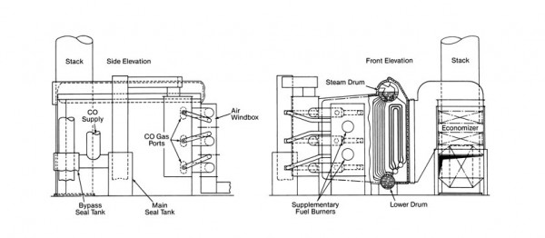
For refineries generating large quantities of CO, field-erected boilers such as the PFI boiler are used. There are also many smaller refineries that have cracking units in the general range of 12,000 barrels (1908 m3) per day or less which produce from 75,000 to 175,000 lb/h (9.5 to 22.1 kg/s) of CO gas. CO boilers for this capacity are often small enough to be shop assembled. A shop-assembled boiler modified for CO firing is shown below. CO gas is admitted through ports in the side walls and front wall to promote mixing and rapid combustion. The burners, for firing supplementary fuel, are located in a refractory front wall and fire into a horizontal furnace. The maximum steam requirements of the cracking unit may occur at normal, full load operation or during startup, depending on the plant steam cycle. The supply of CO is normally not sufficient to generate the maximum amount of steam required and supplementary fuel is then needed.

Supplementary fuel is also required to raise the temperature of the CO gases to the ignition point and to assure complete burning of the combustibles in the CO gas stream.
The following design criteria have been established:
1. The basic firing rate should produce a temperature of 1800F (982C) in the furnace for a suitable residence time to provide safe and stable combustion of the fuels.
2. Air is supplied by the forced draft fan to provide 2% oxygen leaving the unit when burning CO gases and supplementary fuel.
3. Supplementary firing equipment is provided which is capable of raising the temperature of the CO gases to 1450F (788C), the temperature needed for ignition of the combustibles.
Because of possible variations in the combustible and oxygen content of the CO gases, the sensible heat of the CO gases and the amount of supplementary firing, it is impractical to set up a fuel-air relationship. Consequently, it is necessary to directly determine the amount of excess oxygen leaving the unit. This may be determined by an oxygen analyzer.
Water seal tanks or bubble-tight valves are installed upstream of the CO boiler to act as shutoff valves in the large gas lines so that the CO gases from the catalyst regenerator may be passed through the boiler or sent directly to the stack. This permits independent operation of the CO boiler without interfering with the operation of the regenerator. Water seal tanks are preferred to mechanical shutoff dampers because of the high gas temperature, the size of the CO ducts, and the need for leak proof construction.
The operation of the CO boiler is coordinated with that of the catalytic cracker. Normally, the boiler will be required to supply steam for the operation of the catalytic cracking unit and will be started using supplementary fuel. The CO boiler should be started using only the supplementary fuel burners and bypassing the gases from the regenerator to the atmosphere. CO gases should not be introduced into the boiler until it is brought up to temperature because these gases usually are at or below 1000F (538C) and, consequently, tend to cool the furnace. They ignite quite readily and burn with a nonvisible flame. As the CO is introduced to the boiler, it is necessary to reduce the supplementary fuel and the combustion air. This readjustment in the air requirement is determined from the oxygen recorder reading.
The economics of the CO boiler depend on the amount of available heat in the regenerator exhaust compared with an equivalent amount of heat from an alternate fuel. The heat from the CO gases is calculated by taking the sensible heat above an assumed boiler stack temperature plus all of the heat from the combustibles. The additional steam generated in the CO boiler by the supplementary fuel is comparable with the steam generated in a conventional power boiler. Normally, the supplementary fuel requirement will account for one fourth to one third of the output when the temperature of the entering CO gas is maintained at 1000F (538C).
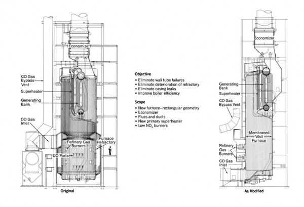
Changes in FCCU catalyst and in process conditions have permitted reductions in the CO content of the gases leaving the unit. These changes also result in the gas temperature to the CO boiler increasing from the 1000F (538C) level to as high as 1450F (788C). Many existing CO boilers have been upgraded to handle the new conditions. Changes have included elimination of combustion zone refractory, use of membraned water walls, and resizing of heat transfer surface. (See figure below.) New heat recovery boilers on FCC units are designed for these new process conditions.
